Reproduced for use by The AutoShrine Network from Twigworker's (Jack Austin) personal site at www.jackscars.net
After a recent on-line post concerning the re-timing of the camshaft on a TR3 engine, I was asked by several folks about the method that I used to determine TDC (Top Dead Center).
There are several ways to accomplish this, but the way that I prefer to do it with the engine assembled is to attach a degree wheel and pointer to the crankshaft and turn the engine one way and then the other until the piston is stopped by a device inserted through the spark plug boss.
Some trial and error is needed until the remaining arc/travel is small enough to deal with but once that dimension reaches something in the neighborhood of thirty degrees it is easy to split the wheel reading and come up with an accurate positioning of the crankshaft and piston.
My purpose here is not to go into the exact details of how all of that is accomplished, but rather just to description of the piston stop device that I use.
Fortunately, and unfortunately, I when this particular job came along I found that I had either misplaced or flat out lost the stop that I have used for years and had to make a new one. The fortunate part is that this gave me the opportunity to take some photos of the parts as they were made and assembled.
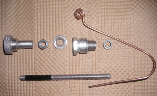
The first shot shows the individual components laid out in the order in which they will be assembled. You will see that the body is made of a spark plug with everything removed except the basic shell. Once it had been stripped I drilled out the center to a loose 5/16".

Parts to build the Piston Stop (TDC) Cam Timing Tool
You will also see a long bolt with it's hex removed and threaded to 5/16" 24 TPI , the end of which has been rounded . At the other end you see a knurled knob that started out in life as a fancy way to hold down the rocker cover on an MG engine.
Near one end of the body there is what appears to be a thick washer, but it really is a 5/16" 24 TPI nut that has been turned down to an outer diameter slightly less than the smallest diameter of the threaded section of the body.
There are also a normal 5/16" nut and a washer that can be used to lock the position of the rod should that be needed.
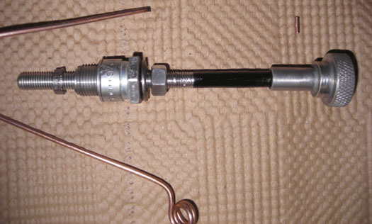
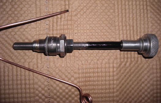
The second picture is of the parts loosely assembled and the third is of the completed tool. As you can see in it, the nut that had been turned down is now solidly brazed to the nose of the body.

Initial loose assembly of TDC Cam Timing Tool

Completed TDC Cam Timing Tool build, nut brazed
If you find that the inside diameteer of the plug body that you use is appropriately small and can be drilled and tapped itself, you can eliminate the turned down nut and the hassel of brazing it to the body. I was using an NGK plug and there was just not enough meat inside the opening to support being threaded.
All of the parts are bits that you can probably find in your junk tray. Any sort of knob could be used or you could just braze a small cross bar onto the end of the threaded rod.
Operation is simple.
Doing the following is made much easier and safer by removing the rocker assembly on a push rod engine or the cam(s) on one with an overhead cam configuration. The case of a push rod motor the cam will rotate a lot more easily if the valve train pressures are removed, and in either situation all of the valves will be closed making it impossible to bend one by having a piston strike it.
- First, get a rough idea of the position of the piston by watching the rocker arms or cam and then roll the crankshaft off of the perceived TDC by thirty degrees or so.
- After installing the degree wheel and pointer with the TDC marking adjusted to the pointer tip, install the stop tool through the plug boss and screw the rod down into the cylinder a bit.
- Next, slowly roll the crankshaft until the piston comes into contact with the end of the stop and note the pointer reading.
- Follow that by turning the crank in the opposite direction until the piston again is stopped by the tool and note the reading again.
- If you never feel the piston being stopped you don't have the tool screwed in enough so try again with it run further in.
- With your two readings combined you now have an arc the center of which is TDC.
- To reach a manageable sized arc repeat the above steps after screwing the rod in a little more. Remember that this is a trial and error process through which you are trying to get the arc down to around twenty or thirty degrees total.
- Once you have achieved that, it is a simple matter to turn the crank one half of that distance and find TDC.
- Once the crank is positioned at TDC you can loosen the crank nose fastener and rotate the degree wheel so that the printed TDC aligns with your pointer and secure it there. Presto, you are dead on TDC!
- From this point, you can go about your business of setting up the camshaft.
One caveat is that when TDC is first determined and before you loosen the degree wheel fastener you MUST find some way to firmly lock the crankshaft into position. Otherwise when you go to loosen the fastener you will turn the crank slightly and all of your efforts will be lost. Use your own imagination to do this, but as I say, it must not allow for even the slightest change in crank position. One simple way is to determine the position of the flywheel relative to the back of the engine and drill and tap a small (3/8" ?) hole in the bell housing that will accept a bolt that can be run through it and jammed against the perimeter surface of the wheel or the ring gear.


After using it once to find TDC I decided to set it up so I could mount my degree wheel again and easily find TDC. Here's what I did before removing the degree wheel.
1. Turn the crank back to 15 degrees BTDC
2. Adjust the positive stop tool to lock against the piston at that spot.
3. Tighten the tools jam nut to lock in that length setting.
4. Remove both the degree wheel and the tool.
Next time I need to re-mount the degree wheel, I screw in the positive stop tool, turn the crank until the piston stops on the tool, then set the wheel to 15 degrees BTDC. Now I can remove the tool, rotate the crank knowing that it is positioned correctly.
is good, but if you are going to degree in a cam it will not be
accurate enough. My guess is that you will end up with a one or two
degree variance due to several possibilities. One would be the
concentricness of the nub of the too. If it has any wobble at all it
will touch the top of the piston at different points. Two, if there is
any crud build up on the piston crown, that will affect the dept of
the nub. Use your method for pretty darned close" needs, but do go through the whole deal if you need to be absolutely spot on.....Jack
Of course no additional miles were put on the car and there is next to no carbon on the piston crown. Nice radius on the tip and no play in the tool.
Of course you could run into a problem each time you find TDC with the stop tool. You have to bump the stop 2 separate times so it has to be sturdy. Removing the head and indicating directly on a clean piston would be the preferred way.
After putting miles on the car I would go through the whole procedure first, and then feel confident in removing and reinstalling the wheel as needed during that session.
Want to leave a comment or ask the owner a question?
Sign in or register a new account — it's free