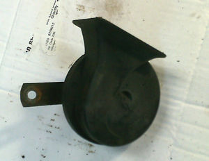
The purpose of this checklist is to describe the operation of the horn circuit and provide a diagnostic checklist. The details apply specifically to the Series III cars but other models are similar.
Circuit Description:
The circuit has three main components:
- The horns themselves,
- a relay (mounted low on the right side inner fender, well forward) and
- the horn push contact in the steering wheel pad.
The horns are always grounded and rely on voltage from the relay to operate. Pushing the horn pad creates a ground path which energizes the relay.
Diagnostic Checklist:
The horn circuit is quite simple to check. The only tools required are a 12 volt test light and several feet of jumper wire.
- First things first....check the two fuses. The #11 fuse in the main fuse box protects the control circuit. An inline fuse in the heavy brown wire above the battery (on LHD cars at least) protects the actual power circuit.
- If the fuses are OK the next step is to see if the horns themselves are operational by circumventing the control circuit. Disconnect the purple/yellow wires from the horns. Using your jumper wire, apply 12 volts to the horns. If the horns do not operate then they are defective or not properly grounded. Check the ground wires and if they are OK then the horns will need replacing. If the horns DO operate correctly by being directly powered then the fault must be in the control circuit. See Step 3.
- Locate the relay and remove the connector plug. Turn the ignition "on" and make the following checks at the connector cavities with your test light. The green wire terminal should have 12 volts. If no voltage then the #11 fuse is blown or you have a wiring/connector fault between the relay and the main fuse box. The brown/purple wire terminal should also have 12 volts (even with the key "off"). If no voltage here then the inline fuse is blown or you have a wiring fault between the relay plug and the fuse. If these checks are OK, see Step 4.
- Next check the ground circuit for the relay. Arrange your test light to check for ground and locate the connector terminal associated with the purple/black wire. Have a helper push the horn. Your test light should light up indicating a good ground. If there is no ground then there is a wiring fault between the relay and the steering column or a ground fault in the column. (See Step 6). If the ground circuit is OK.......
- Plug the relay connector back onto the relay. You'll need to check for voltage at the purple/yellow wire....which ultimately connects to the horns. Back probe the connector at the cavity associated with the purple/yellow wire (that is, insert your test light probe into the cavaity from the same direction as the wire enters. Make sure the probe touches the metal terminal.) and have a helper push the horn button. You should get 12 volts at this terminal. If no voltage then the relay is faulty and should be replaced. If voltage is OK but the horns don't work then you have a wiring fault on the purple/yellow wire from the relay to the horns.
- You're here because the ground circuit test in Step 4 indicated a problem. The ground path is completed by pushing the horn pad. Before checking the horn pad look at the right side of the steering column. You'll see to metallic grounding tabs. Check that these are in firm contact with the column. Clean and lightly re-grease the contact points. Next, remove the horn pad by removing the two screws from behing the steering wheel. Examine the center contact and ensure it is clean and has enough tenson to contact the sliding rod in the center of the column.
I might add, in conclusion, that if all the above wiring tests are confirmed OK and the horns themselves are known good, then the relay must be faulty.


No comments have been posted yet...
Want to leave a comment or ask the owner a question?
Sign in or register a new account — it's free